
Booster engine with the cover removed to show the mechanism. The driven axle is on the right; the booster normally hung behind it. This is a Franklin Railway Supply Co. model, one of the most common. Click to enlarge. (Locomotive Cyclopedia of American Practice, Public domain, Wikimedia Commons.

FRANKLIN BOOSTER
Invented in 1918 by Howard L. Ingersoll, assistant to the President of the New York Central Railroad, the locomotive booster for steam locomotives is a small two-cylinder steam engine back-gear-connected to the trailing truck axle on the locomotive or one of the trucks on the tender. A rocking idler gear permits it to be put into operation by the driver (engineer). A geared booster engine drives one axle only and can be non-reversible, with one idler gear, or reversible, with two idler gears. There were variations built by the Franklin company which utilized side rods to transmit tractive force to all axles of the booster truck. These rod boosters were predominately used on the leading truck of the tender, though there is an example of a Lehigh Valley 4-8-4 using it as a trailing tender truck.
A booster engine is used to start a heavy train or maintain low speed under demanding conditions. Rated at about 300–500 horsepower (220–370 kW) at speeds of from 10 to 35 mph (16 to 56 km/h), it can be cut in while moving at speeds under 12–22 miles per hour (19–35 km/h) and is semi-automatically cut out via the engineer notching back the reverse gear or manually through knocking down the control latch up to a speed of between 21 and 35 mph (34 and 56 km/h), depending on the model and gearing of the booster. A tractive effort rating of 10,000–12,000 pounds-force (44–53 kN) was common, although ratings of up to around 15,000 lbf (67 kN) were possible.
Tender boosters are equipped with side-rods connecting axles on the lead truck. Such small side-rods restrict speed and are therefore confined mostly to switching locomotives, often used in transfer services between yards. Tender boosters were far less common than engine boosters; the inherent weight of the tenders would decrease as coal and water were consumed during operation, effectively lowering the adhesion of the booster-powered truck.

Diagram showing how a booster is installed and connected. Click to enlarge.
(1922 Locomotive Cyclopedia of American Practice, Public domain, via Wikimedia Commons)
Reasons for use
The booster was intended to make up for fundamental flaws in the design of the standard steam locomotive. To start off, most steam locomotives do not provide power to all wheels. The amount of force that can be applied to the rail depends on the weight on the driven wheels and the factor of adhesion of the wheels against the track. Unpowered wheels are generally needed to provide stability at speed, but at low speed they are not required, so they effectively 'waste' weight which could be used for traction. Therefore, the application of a booster engine to the previously unpowered axle meant that overall starting tractive effort was increased with zero penalty to the adhesion levels of the main engine.
Additionally, the "gearing" of a steam locomotive is fixed, because the pistons are linked directly to the wheels via rods and cranks. Therefore, a compromise must be struck between ability to exert high tractive effort at low speed and the ability to run fast without inducing excessive piston speeds (which would cause failure), or the exhaustion of steam. That compromise means that, at low speeds, a steam locomotive is not able to use all the power the boiler is capable of producing; it simply cannot use steam that quickly, so there is a substantial difference between the amount of steam the boiler can produce and the amount that can be used. The booster engine enabled that wasted potential to be put to use.
The increased starting tractive effort provided by the booster meant that, in some instances, railroads were able to reduce the number of, or eliminate entirely the use of additional helper locomotives on heavier trains. This resulted in lower operating and maintenance costs, higher locomotive availability and productivity (ton-miles), and ultimately, greater profitability.

A typical Franklin Booster printed ad, from Railway Age, 1931. Click to enlarge.
(Railway Age, Public domain, W. Lenheim Collection)
Disadvantages
Boosters were costly to maintain, with their flexible steam and exhaust pipes, idler gear, etc. Improper operation could also result in undesirable drops in boiler pressure and/or damage to the booster. The booster and its associated componentry also added several tons of weight to the locomotive which would be considered "dead weight" at speeds above which the booster could not be used. Additionally, if the booster suffered a failure where the idler gear could not be disengaged, the entire locomotive would be speed restricted to 20 mph or less, until it could be taken out of service to facilitate repairs, decreasing locomotive availability.
Calculating tractive effort and operating speeds
A rough calculation of booster tractive effort could be made with the following formula:
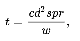
where
t is tractive effort in pound-force
c is the coefficient representing mean effective pressure, normally set to 0.80
d is the piston diameter in inches (bore)
s is the piston stroke in inches
p is the working pressure in pounds per square inch
r is the booster gear ratio
w is the diameter of the trailing wheels to which the booster is geared in inches
The typical locomotive booster employed a pair of 10-inch-bore (250 mm) by 12-inch-stroke (300 mm) cylinders. Available gear ratios and associated operating speeds for both the Franklin type C and type E booster models are detailed in the table below.
Locomotive booster gear ratios and associated operating speeds
Franklin Type C-1 & C-2
Gear ratio: 2.571
Maximum cut-in speed: 12 mph (19 km/h)
Maximum operating speed: 21 mph (34 km/h)
Franklin Type E & E-1
Gear ratio: 2.71
Maximum cut-in speed: 15 mph (24 km/h)
Maximum operating speed: 25 mph (40 km/h)
Gear ratio: 2.25
Maximum cut-in speed: 18.5 mph (29.8 km/h)
Maximum operating speed: 30 mph (48 km/h)
Gear ratio: 2.00
Maximum cut-in speed: 22 mph (35 km/h)
Maximum operating speed: 35 mph (56 km/h)
Usage
North America
The booster saw most use in North America. Railway systems elsewhere often considered the expense and complexity unjustified.
Even in the North American region, booster engines were applied to only a fraction of all locomotives built. Some railroads used boosters extensively while others did not. The New York Central was the first railroad to use a booster in 1919 and remained a proponent of the device, applying them to all of its high-driver 4-6-4 Hudson locomotives to increase their acceleration out of stations with crack passenger trains. The rival Pennsylvania Railroad, however, used few booster-equipped locomotives. Similarly, the Chesapeake & Ohio specified boosters on all of its Superpower locomotives aside from the Allegheny to increase tonnage ratings over some of the hilly terrain found on their main lines, while rival Norfolk & Western experimented with boosters briefly and found their cost unjustified, instead choosing to increase engine tractive effort through the raising of boiler pressure.
Canadian Pacific Railway rostered 3,257 steam locomotives acquired between 1881 and 1949, yet only 55 were equipped with boosters. 17 H1 class 4-6-4s, 2 K1 class 4-8-4s and all 36 Selkirk 2-10-4s.


